The CycWEC is the first wave energy system designed to deliver utility-scale power in the real world.
Utility-Scale Wave Energy
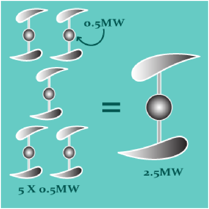
The CycWEC is a new class of wave energy converter designed to deliver reliable, predictable, and cost-competitive power at utility scale. Instead of fighting the ocean’s surface like traditional devices, the CycWEC operates below it, where the energy is most consistent and storm damage is minimal. Each unit generates 2.5 MW, with a linear scaling path to 5 MW and beyond, comparable to a wind turbine. With up to 95% wave energy capture efficiency, it overcomes the scaling and survivability challenges that have held wave energy back so far.
How the CycWEC Works
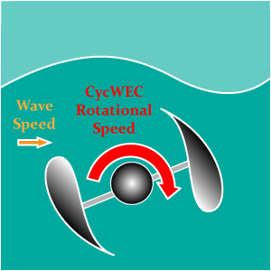
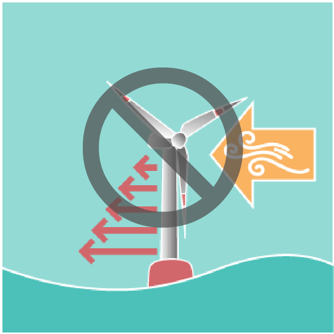
The CycWEC uses rotating hydrofoils to convert the orbital motion of waves into clean, continuous power. Two hydrofoils spin on a horizontal axis below the surface, generating lift forces that are turned into torque and then electricity. A real-time control system synchronizes blade pitch and rotation speed with each passing wave, keeping the system perfectly in phase to maximize energy capture. By operating underwater, it taps into the most stable part of the wave while avoiding surface damage and losses.
Twelve Breakthrough Features
The CycWEC solves problems that stopped every previous wave energy attempt. These twelve unique features work together to deliver utility-scale power while surviving storms, minimizing costs, and enabling deployment anywhere strong wave climates meet electricity demand.
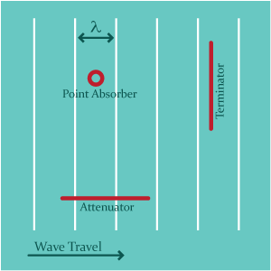
Wave Terminator Design
Aligns with wave crests to capture maximum energy. Power output scales linearly with device width, making true utility-scale generation practical.
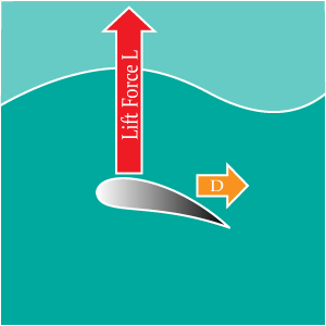
Hydrofoil Lift
Applies the same lift physics as turbines and aircraft to generate forces up to 10× higher than drag systems, with far lower energy loss.
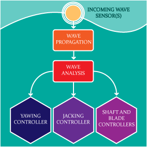
Feedback Flow Control
A proprietary algorithm adjusts blade pitch and rotation speed in real time for each wave, achieving 95% capture efficiency versus less than 5% without control.
Device Scalability
Fewer units produce the same output, driving down per-device costs. Fewer components mean simpler maintenance and fewer potential failure points.
High Rotational Speed
Hydrofoils operate faster than water flow, and forces scale with velocity squared. This enables smaller devices to produce equivalent power.
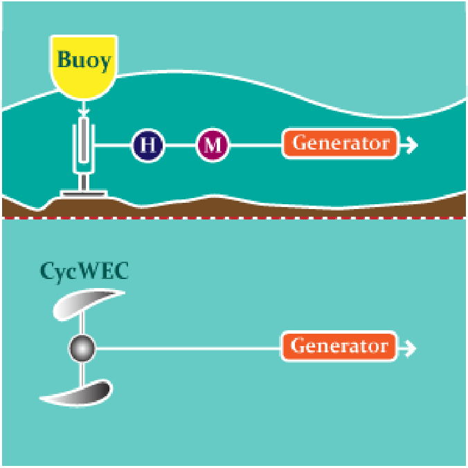
Direct Drive Generator
Converts wave energy directly to shaft power and electricity, removing hydraulic steps. Fewer conversions mean higher efficiency and lower system cost.
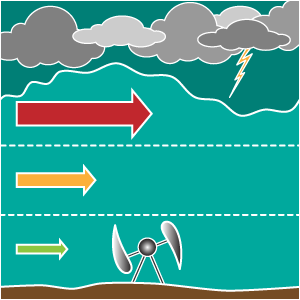
Storm Survival
Submerges deeper during storms where wave energy weakens. Lower storm loads eliminate the need to overbuild, improving durability and lowering cost.
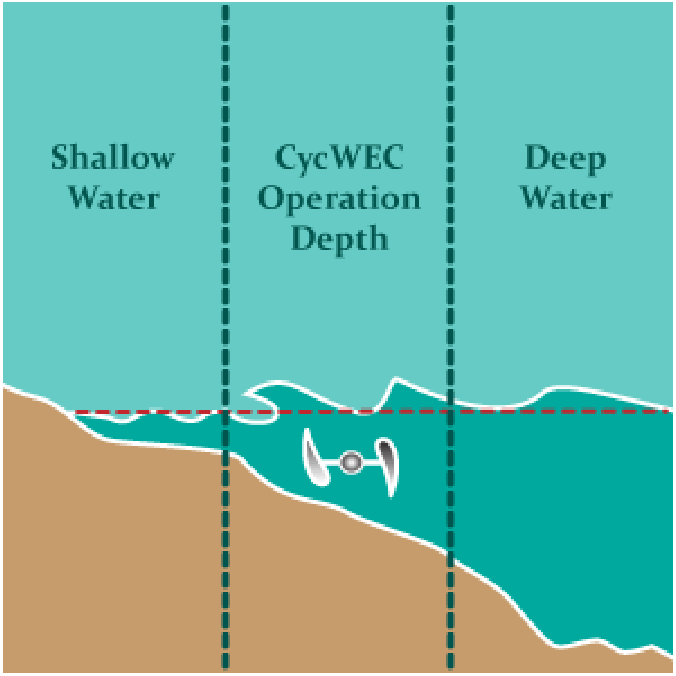
Intermediate Water Operation
Deploys at 50–100 meters depth, where wave energy remains strong but installation costs are much lower than in deep ocean sites.
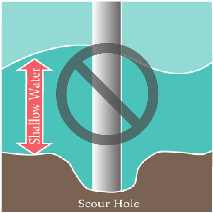
Scour Avoidance
Intermediate depth prevents the seabed erosion that affects shallow-water systems, maintaining structural integrity without costly reinforcement.
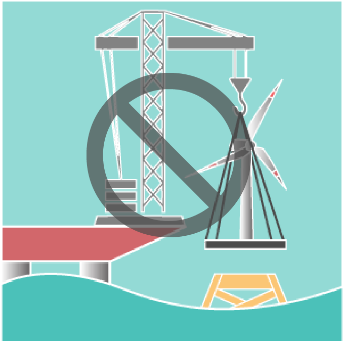
Simple Deployment
Self-floating structure tows with a tugboat and installs using its own mooring system. No cranes or jacking rigs needed, enabling flexible global deployment.
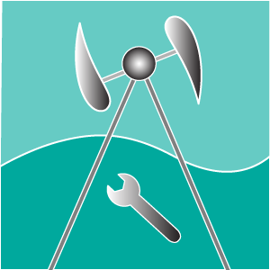
On-Site Maintenance
Jacking mechanism lifts the device fully above water for servicing. Eliminates dive teams and heavy lift vessels, minimizing downtime and maintenance costs.
Reduced Structural Weight
Mooring avoids bending loads by working only in tension and compression. This reduces structural weight, fatigue, and construction costs while increasing reliability.
Performance Metrics
2.5MW
Generator power
~5.4 GWh
Annual production
38%
Capacity factor
95%
at design point Wave energy capture
CycWEC Specifications
Rotor diameter
12m
Hydrofoil span
60m
Hydrofoil chord
6m
Water depth
50-100m
Mooring footprint
100x100m
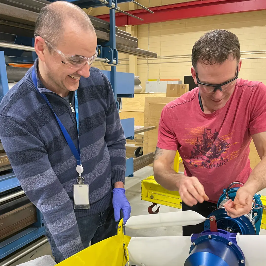
Proven in the Lab
Over fifteen years of testing, trials, and simulations have validated the performance, control systems, and durability of the CycWEC. Ongoing testing at the National Research Council Canada continues to build on this foundation, paving the way toward commercial deployment.
The CycWEC combines hardware patents with proprietary control software to safeguard its competitive edge. Eighteen patents cover the core systems, deployment, and energy capture methods. The control algorithm makes the difference between 95% energy capture and just 5% without it. Together, these protections create a powerful barrier to replication.